Fluidguard Machinery Equipment Co., Ltd. amy@aida-machinery.com
Call Us : 0086-15137376132
Fluidguard Machinery Equipment Co., Ltd. amy@aida-machinery.com

Call Us : 0086-15137376132
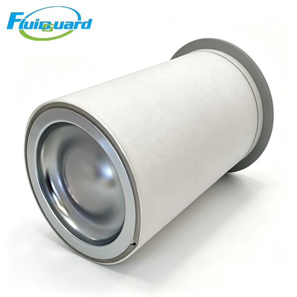
Model : OS5218
Type : Oil Separators Filters
Replacement for : OS5218
Automotive large-component electrostatic painting workshops, heavy metal fiber laser cutting factories, large plastic injection molding production lines, bulk food & beverage sterile packaging pneumatic systems, textile mill central compressed air supply, medium-large pharmaceutical aseptic producti
Part numbers marked "replacement" are not affiliated with the original manufacture.
Fluidguard is a technology-based enterprise integrating industry and trade, with strong technical strength and production capacity.
Core Technical Specifications
Filtration Grade: Primary submicron high-efficiency coalescing separation for large-flow industrial screw compressors
Absolute Separation Precision: 0.1 μm micro oil mist aerosols
Oil Mist Capture Efficiency: ≥99.999% interception rate for all oil particles ≥0.1 μm
Filter Media: Imported multi-layer gradient HV borosilicate glass fiber composite media, hydrolysis resistant, continuous temperature resistance up to 108°C
Max Continuous Working Pressure: 1.0 MPa
Continuous Operating Temperature Range: -10°C ~ +108°C
Clean low-dust factory workshop: 4,000–6,000 operating hours or 12 months
Heavy dust, high temperature, 24/7 full-load continuous production: Shorten service life to 3,000–4,500 hours
Mandatory Replacement Trigger: Differential pressure ΔP ≥ 0.08 MPa or obvious oil carryover in downstream large-diameter air pipelines
Differential Pressure Thresholds
Initial pressure drop of brand-new separator: ≤0.02 MPa
Alarm replacement differential pressure: ΔP ≥ 0.08 MPa
Structural Construction Features
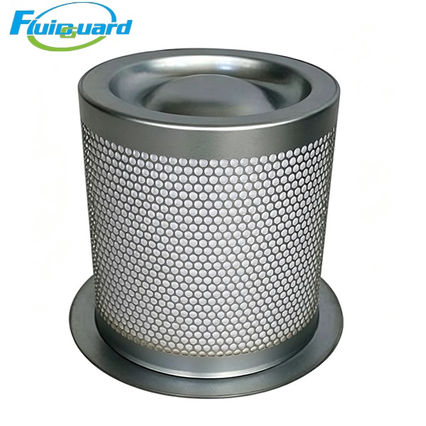
Outer perforated galvanized steel mesh jacket: Anti-rust, resistant to long-term erosion of high-temperature oil vapor & acidic condensate inside oil tank
Thickened perforated central support tube: Anti-collapse deformation under large-volume high-speed airflow surges
Integrated flat steel flange + full-face heat-resistant fiber sealing cushion, zero air/oil bypass leakage
Central built-in micro oil return drain pipe: Collects coalesced liquid oil and refluxes back to tank oil sump to avoid secondary liquid re-entrainment by turbulent high-speed airflow
Key Product Advantages
Extra wide pleated filtration area stores massive oil sludge, carbon deposits and liquid contaminants; differential pressure rises gently throughout full service cycle even under continuous heavy oil load. Layered coalescing structure aggregates micro oil droplets into continuous liquid film for gravity reflux, maintaining consistent ultra-high separation efficiency without performance decay.
Integrated central oil return pipeline eliminates secondary oil carryover risk
Coalesced liquid oil flows down dedicated central drain tube directly back to tank bottom oil sump, preventing separated oil from being blown back into clean air stream by large-volume turbulent airflow, sustaining stable low oil carryover performance for full service life.
Full galvanized anti-corrosion & anti-static metal framework adapts to harsh humid high-temperature tank environments
All metal support frames adopt galvanized anti-rust coating, resisting long-term erosion of high-temperature oil vapor and acidic condensate inside oil tank; built-in static conductive structure eliminates hidden static accumulation fire hazard inside the separator element.
Standard multi-hole flange quick maintenance design
Original matched flange perfectly fits standard large oil tank bolt layout. After full compressor shutdown, pressure venting and partial oil draining, disassembly and installation can be finished within 12 minutes without pipeline reconstruction.
Working Principle
High-temperature large-flow oil-air mixed gas discharged from screw rotors enters outer cavity of separator element. Large oil droplets collide with outer steel perforated jacket and drop into oil tank by gravity for primary coarse separation.
Fine submicron oil mist aerosols penetrate multi-layer gradient glass fiber media; tiny oil particles collide, aggregate and coalesce into continuous liquid oil films on fiber surfaces.
Coalesced liquid oil flows downward along media layers, converges into central built-in oil return tube, and refluxes back to oil sump for circulation reuse.
Clean low-oil compressed air (residual oil ≤3 ppm) passes through inner core support tube and flows out of oil tank to downstream air treatment equipment and production terminals.
When media is fully saturated with carbon sludge and oil deposits, differential pressure rises sharply; excessive pressure difference may crack glass fiber media and cause massive oil carryover failure.
Application Scope
Automotive large-component electrostatic painting workshops, heavy metal fiber laser cutting factories, large plastic injection molding production lines, bulk food & beverage sterile packaging pneumatic systems, textile mill central compressed air supply, medium-large pharmaceutical aseptic production gas supply, heavy machinery processing pneumatic tool stations.